Product Details
Product name: GCS low voltage switch
Detailed description:
GCS type low-voltage withdrawable switchgear (hereinafter referred to as the device) is designed and developed by the two joint design teams according to the requirements of the industry authorities, the majority of power users and the design unit, which meets the national conditions, has high technical performance indicators, and can adapt to the power market. The low-voltage withdrawable switchgear that is needed for development and can compete with the existing imported products. This device has been widely used by electric power users.
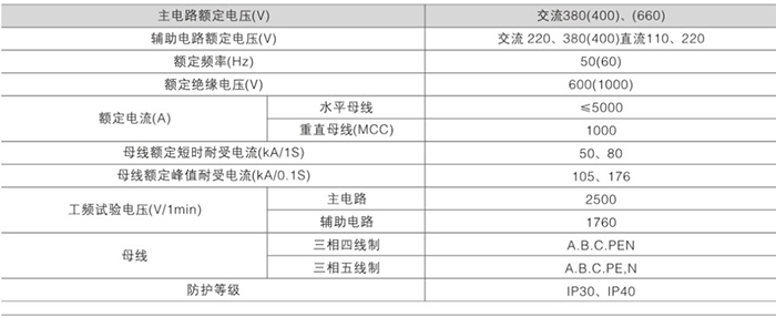
The device is suitable for power distribution systems in power plants, petroleum, chemical, metallurgy, textile, high-rise buildings and other industries. In large power plants, petrochemical systems and other places with a high degree of automation and computer interface requirements, as a three-phase AC frequency of 50 (60) Hz, rated working voltage of 380 (400) V, (660) V, and rated current of 5000A Low-voltage complete set of power distribution equipment used for power distribution, centralized motor control, and reactive power compensation in power generation and power supply systems and below. The basic organization of the device is shown in Figure 1.
The design of the device complies with the following standard IEC439-1 "Low-voltage switch and control equipment"
GB7251 "Low-Voltage Complete Switchgear"
Product use environment
1. The ambient air temperature is not higher than +40℃. Not lower than -5°C. The average temperature within 24 hours shall not be higher than +35°C. When it exceeds, the capacity should be reduced and run according to the actual situation.
2. For indoor use, the altitude of the place of use shall not exceed 2000m.
3. The relative humidity of the surrounding air does not exceed 50% when the highest temperature is +40℃, and a larger sealing temperature is allowed at a lower temperature. For example, it is 90% at +20℃, and it should be considered that the temperature may change The effect of condensation occurs accidentally.
4. The inclination between the device and the vertical surface does not exceed 5% when the device is installed. And the whole group of cabinets is relatively flat (in accordance with GBJ232-82 standard).
5. The device should be installed in a place where there is no severe vibration and impact, and where the electrical components are not corroded.
6. When the user has special requirements. It can be resolved through consultation with the manufacturer.
Model and meaning

The main technical parameters

The main circuit
The main circuit scheme of the device has 36 groups and 87 specifications. Does not include plans and specifications derived from changes in auxiliary circuit control and protection:
The main circuit scheme is selected after soliciting the opinions of the majority of design, manufacturing, testing and use departments, including the needs of power generation, power supply and other power users, and the rated working current is 5000A. It is suitable for the selection of distribution transformers of 2500kVA and below. .
In addition, a capacitor compensation cabinet is designed to meet the needs of power supply and use to improve the power factor. Considering the needs of comprehensive investment, the reactor cabinet is designed.
Auxiliary circuit
The GCS auxiliary circuit atlas is compiled according to the relevant design requirements and regulations. There are 120 auxiliary circuit schemes in total. It is divided into two volumes. The first volume (AC operation part) is divided into 63 schemes, and the second volume (DC operation part) has a total of 57 schemes.
The auxiliary circuit scheme of the DC operation part. Mainly used for the low-voltage plant (used) system of the power station of the power generation plant: when compiling, it has been considered suitable for the low-voltage plant system of 200MW and below and 300MW and above capacity units, working (standby) power inlets, and power feeders And the general control method of the line of the motor.
The auxiliary program of the AC operation part is mainly used for the low-voltage system of the substation of factories and mines and high-rise buildings. It can be used directly in engineering design.
The DC control power supply is DC 220V or 110V, and the AC control power supply is AC 380V or 220V. It is a complete cabinet composed of drawer units. The 220V control power supply is drawn from the public control power supply provided by the control transformer in this cabinet. The public control power supply adopts an ungrounded control transformer, and a 24V power supply is reserved for use when a weak current signal is needed.
The installation location of the watt-hour meter, the introduction method of voltage and other installation and use requirements are detailed in the "Compilation Instructions" of the auxiliary circuit diagram.
Busbar
In order to improve the dynamic thermal stability of the busbar and improve the temperature rise of the contact surface, the installation adopts TMY-T2 series hard copper bars. The connection parts of the copper bars must be pressed and tinned, and full-length tinned tin is recommended. Full-length silver-plated copper bus bars can also be used.
Horizontal bus
The horizontal busbar is placed in the busbar compartment at the rear of the cabinet. 3150A and above are upper and lower double layers, 2500A and below are single-layer fabrics, each phase is composed of 4 or 2 busbars, which greatly improves the short-circuit strength of the busbar.
The horizontal busbar copper bars of the device are selected as shown in the table below

The neutral grounding busbar adopts hard copper bar
The specifications of through-level neutral grounding (PEN) or grounding + neutral wire (PE+N) are shown in the table:
